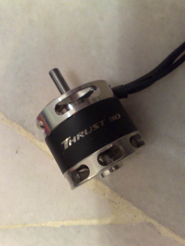
Here are the step by step pictures on how to remove and replace the motor shaft.
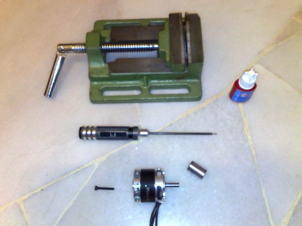
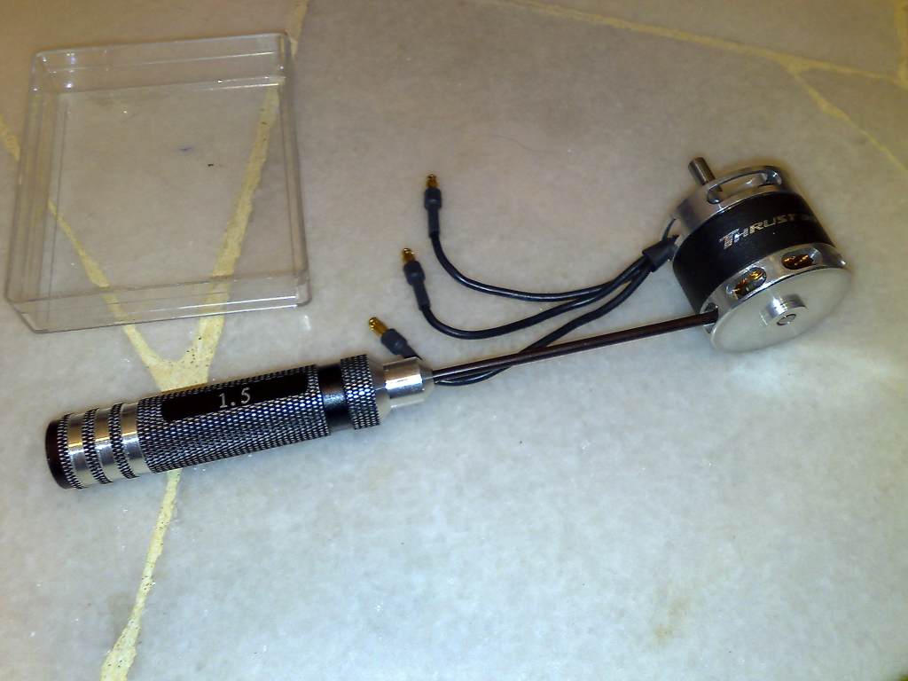
Tools required in preparation are as follows:
1. Vice or even better a bench / press drill
2. A Good 1.5mm Hex wrench
3. A bolt or short metal shaft with a diameter smaller than the motor shaft.
4. A box wrench with a diameter slightly larger than the motor shaft.
5. Blue Thread lock
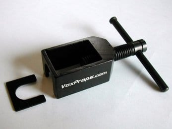
6. Vox prop adapter puller to remove the prop adapter
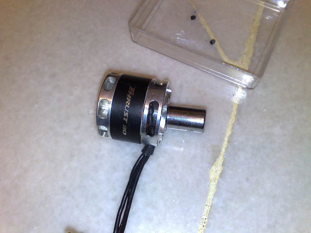
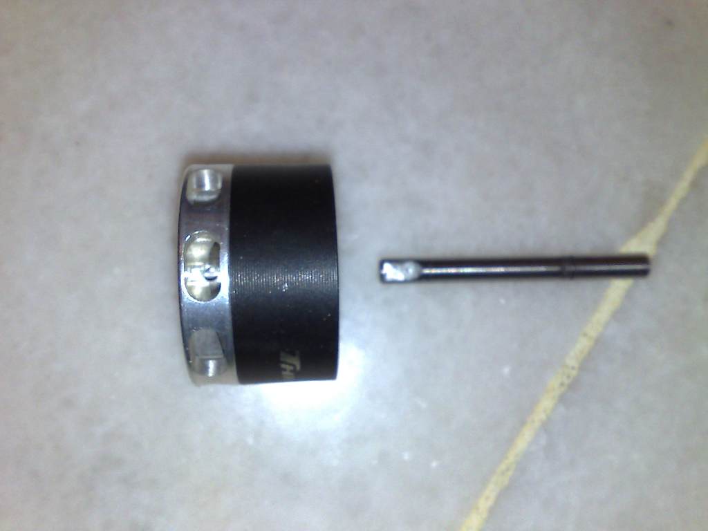
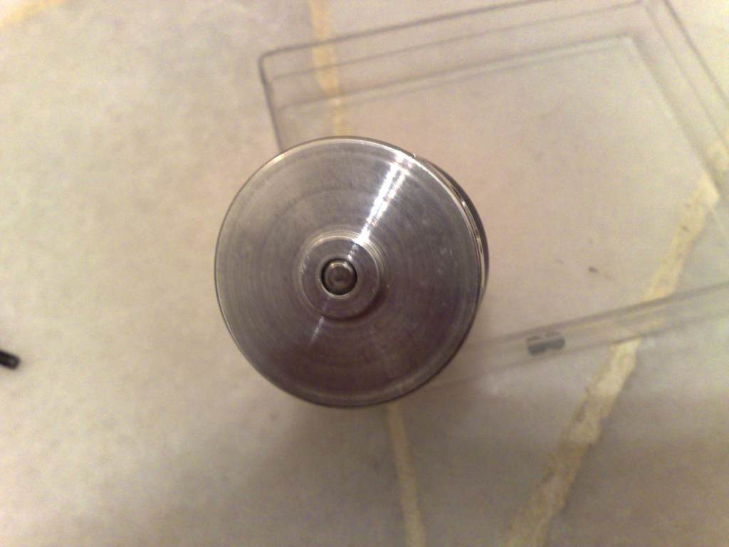
Step 1. Use the Vox prop adapter puller to remove the prop adapter.
Step 2 Tools needed to replace the motor shaft.
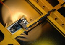
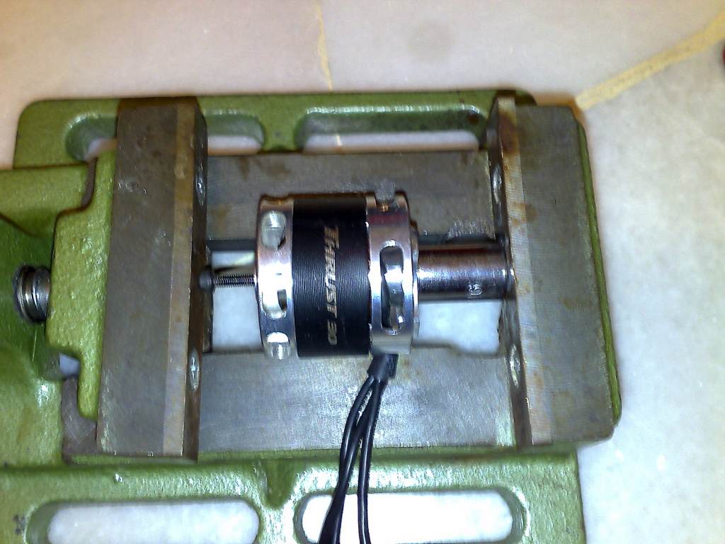
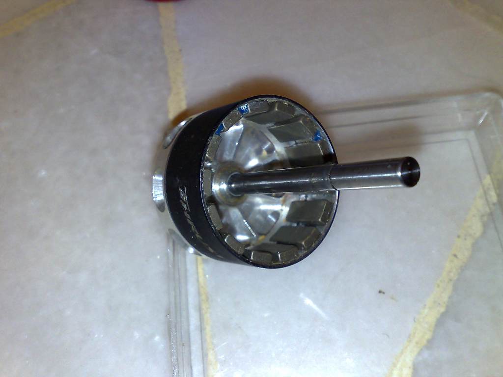
Step 3 Undoing the two 1.5mm grub screws. Ensure a good hex wrench is used to prevent damage to the grubscrew.
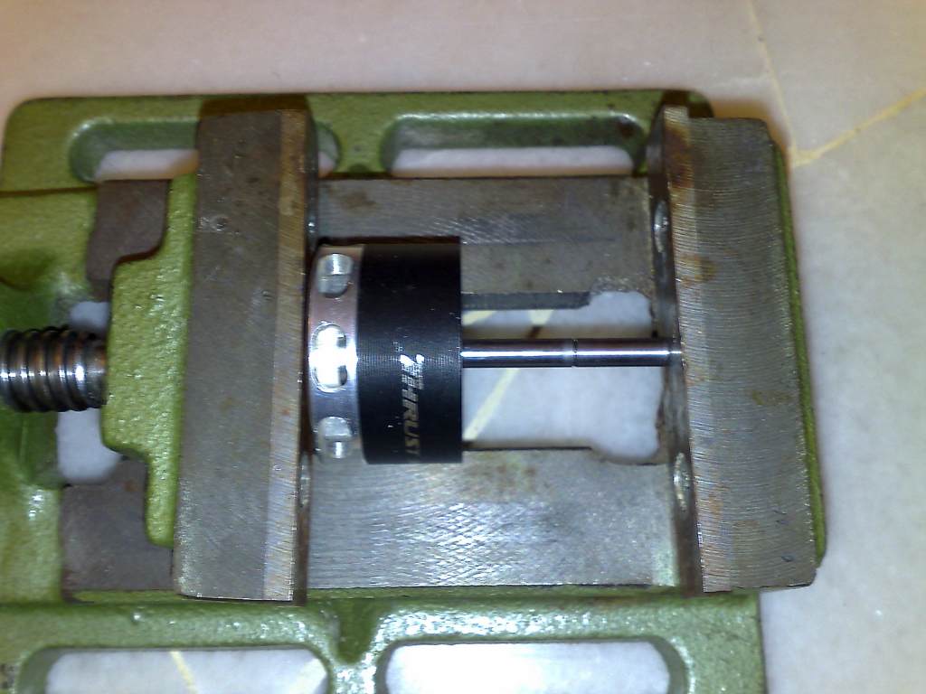
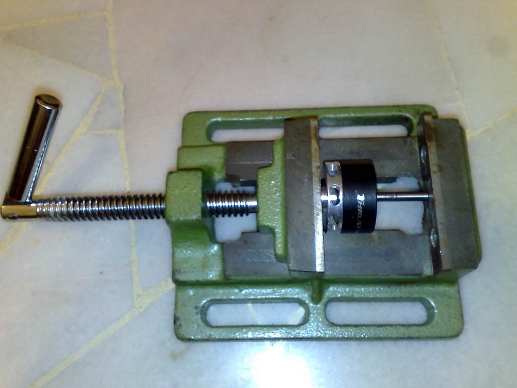
Step 4 Inserting the box wench over the motor shaft. (The box wrench needs to be long enough to allow the shaft to fully travel out of the endbell shaft boss)
Step 5 Placing the bolt at the rear of the endbell and placing the motor into the vice in preparation to press the shaft out.
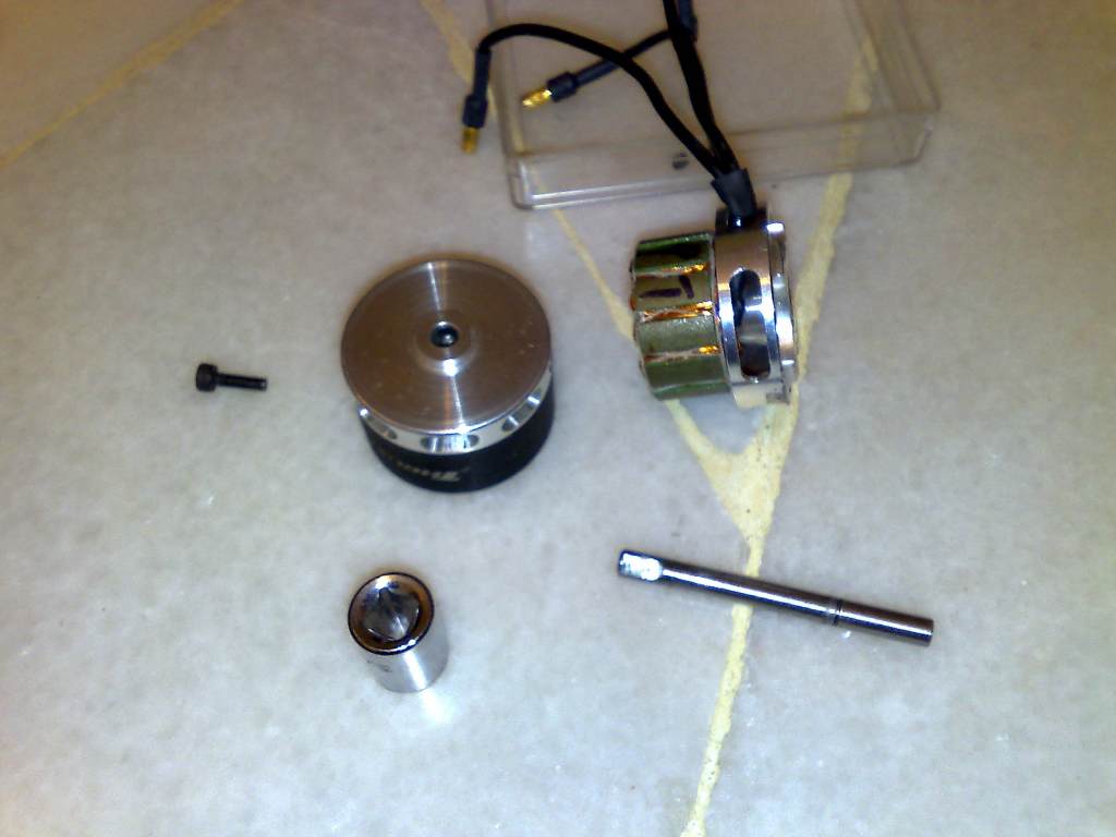
Step 6 Motor shaft safely extracted, this can be done even more accuratelly on a bench drill
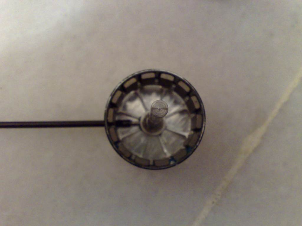
Step 7. Align the flat of the shaft with the grubscrew hole in preparation to insert a new shaft.
Step 8. Gently press the shaft in by hand till it seats without falling out.
Step 9 Place the end bell and shaft into the vice and make sure the endbell sits squarely on the jaw.
Step 10 Begin pressing the shaft in.
Step 11 Motor shaft properly seated flushed with the motor endbell shaft boss.
Step 12 Apply a little blue loctite to the grub screw. ONLY apply to the first 3 threads and no more.
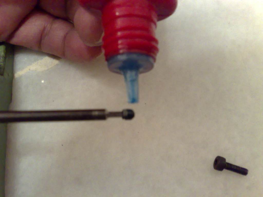
Step 13 Insert the grubscrew into the screw hole and tighten the screw until it sits firmly. DO NOT apply too much force on the wrench or you will strip the threads or grubscrew.
Step 14. Reassemble the motor. (You may choose to also lubricate the bearings at this stage)
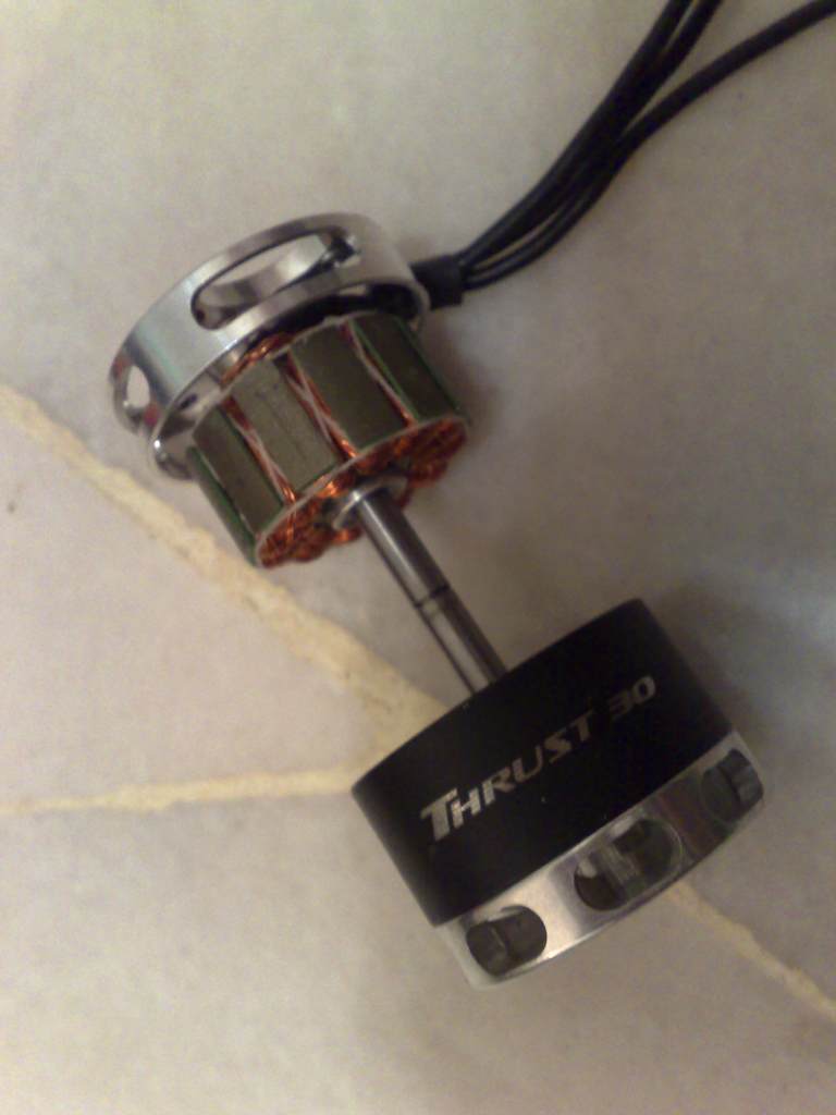
Step 15 A completed assembly.
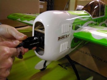
Step 17. Motor happily back in the office and ready to go test the motor rotation prior to reinstalling the prop and cowl.