Prior to strating on the assembly you need the following:-
- A pair of scissors
- disposable lighter
- Good quality thin CA e.g. Zap Thin CA (Pink Bottle)
- Sand paper
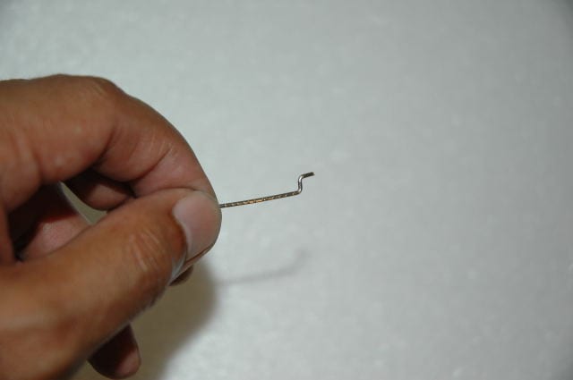
Step 1.
Lightly sand the end section of the CF pushrod along the area where the metal Z-bend would be glued to. (This provides a much stronger glue bond)
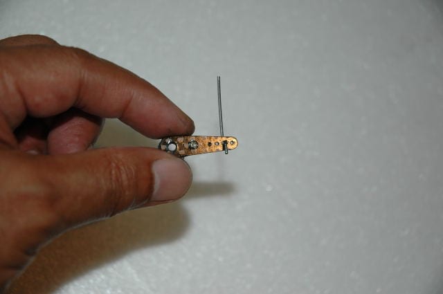
Step 2.
Take the metal Z-bend and gently “drill” the hole in both the CF servo arm extension and CF control horn larger and gently work the z-bend in. Do not use force. Also do not use a drill to enlarge the hole as this can risk enlarging the hole too much and risking inducing slop in the controls later.
Step 3
Take the supplied heat shrink tubing and snip 5 mm off and thread the long section into the CF push rod. Then take the 5mm tube that you snipped off and insert it into the CF pushrod.
Now place the metal z-bend at the end of the CF push rod and slip the 5mm heat shrink tubing and shrink it to help you temporarily hold it in place.
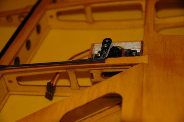
Step 4
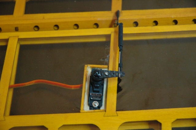
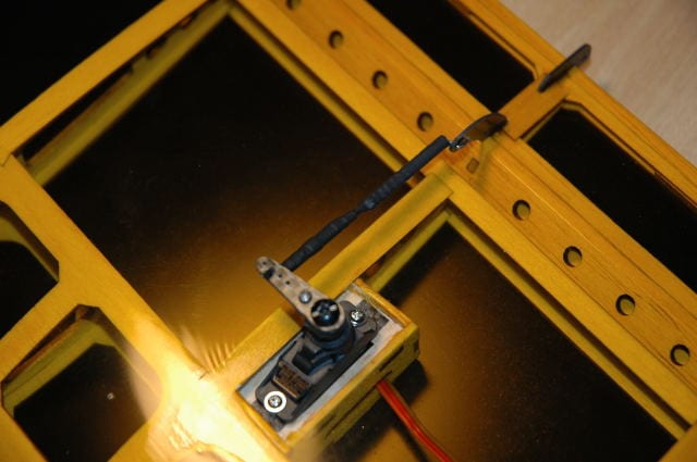
Tape your control surface in the neutral position and install the CF pushrod as per the manual.
Step 5
Adjust the servo arm till it is precisely 90 degrees to the CF pushrod. (Tip:- This will give you linear movement).
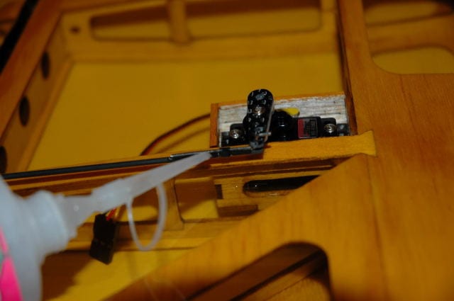
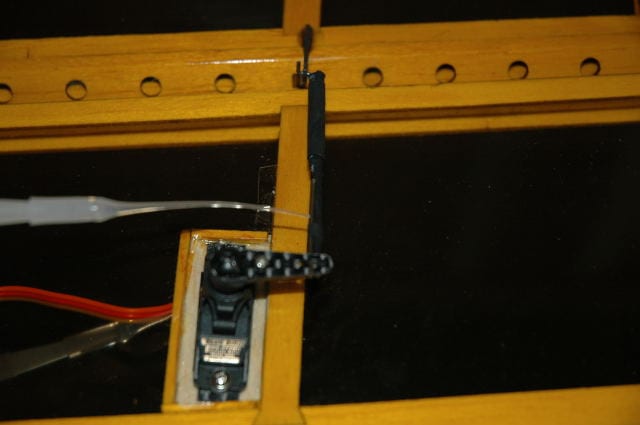
Step 6.
Once satisfied with the servo arm alignment, apply a tiny drop of thin CA to the metal linkage to temporarily tack it down, Allow the CA to set.
Step 7
Once the CA is set, cxarefully remove the linkage assembly and appply a tiny drop of CA near the end of the z-bend on the push rod. Then place the end of the thread and let the CA set to temporarily hold it in place.
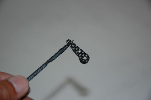
Step 8
Once the CA is set, hold the string with a little tension and carefully wind it over the z-bend and pushrod and tack the other end with CA to hold everything in place.
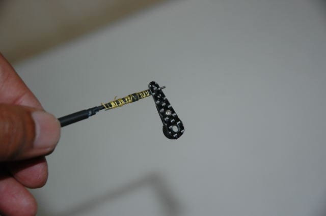
Step 9.
Now apply thin CA over the entire length of the wrapped end and slip the longer heat shrink tubing over it and immediately apply heat to shrink it in place.
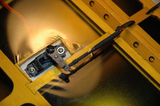
Step 10
Once the CA is set, install the linkage and the job is done.
Tip:- Also apply a drop of thin CA to the factory installed side of the Z-bend. This provides added insurance to ensure gluing mistakes are eliminated and a full proof CF linkage assembly.