How balancing cables are connected to Lipo Packs
Due to the non-standardization of current lipo manufacturers, there is no universal form factor for the balancing plugs and this becomes quite a nightmare for most EP enthusiasts owning a several brands of battery packs.
Although the JST-HXT form factor appears to be the most common “standard” adopted, there are still many lipo manufacturers who adopt their own plug form factor that may or many not be compatible with some balancers available off the shelf.
As such, form factor compatibility is either attained through the purchase of special adapter modules (if available) or at worst needing for the balancing harness to be modified or grafted with an off the shelf compatible plug.
Modifying the balancer plugs to conform to the balancer ports.
In order to modify the balancer plugs to confirm to a specific balancer, we need to understand how balancing harness are typically wired up.
For a 3S (3 cell) lipo pack, balancing connectors will need to have provisions for at least 4 cables (Cell 1 +ve, Cell 1 -ve/Cell 2 +Ve, Cell 2 -ve/Cell 3 +Ve and Cell 3 -Ve) :- Total 4 wires. They are usually one cable more than the number of cell count as a rule of thumb though some balancer modules do utilize more cables at time. It’s advisable to refer to the balancer’s instruction manual in order to understand the wiring configuration before you begin modification because of the risk associated with wrong polarity and short circuits. Remember that though balancing cables are usually smaller in gauge, they are STILL connected to the battery terminals and thus carries the same risk as working on the main battery cables. This means that you are working with LIVE cables!
The simple cable connection are shown in the sketch below
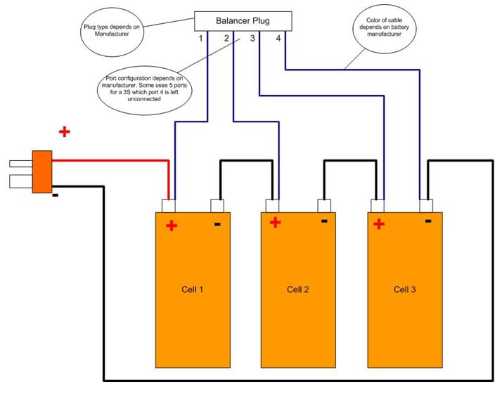
For safety reasons, please do not assume that the polarity of the cables shown in the figure above is the same as what is on your pack and its best to use a DC volt meter to verify to be absolutely sure that what has been wired at the factory is actually correct and could be prone to human error no matter how remote that is. Therefore ASSUME NOTHING! Always check and double check.
Step 1.
Read your balancer’s manual and confirm the wiring configuration of your balancer. Note that on some balancers, they may have more cables than what is shown on the diagram above as they may use a common base plug that accommodates several cell counts (i.e. 1S, 2S, 3S, 4S, 5S, 6S etc). Note carefully the configuration that conforms to the cell count of the battery you are about to modify.
Step 2
Make a sketch of the wiring connection of your battery as you verify with the voltmeter to ensure they are also wired correctly. Mark each cable as you go along. Don’t assume since its very to get the wires mixed up especially when they are the same color.
Step 3
Disconnect the first cable (either by cutting the cable at the balancer plug or removing the pin) If you are removing the pin, then be extra careful not to touch the other pins. ONLY disconnect one wire at the time.
Step 4
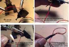
Strip about 5-10mm of insulation of the cable you have just cut to expose the bare wire.
Step 5
Connect, solder and insulate (with heat shrink tubing) that cable to the cable of the new compatible plug. Repeat Step 3 to 5 until you have successfully connected all the balancing harness of the battery to the new plug.
Step 6
Make a final check with a DC Voltmeter to re-confirm the order of the cables and you are done.